|
|
Western Instruments N88-9-I Bridging Pit Depth Gauge System up to 28-1/2" Long, 2 Magnetic Hold Downs, Inch Dial Indicator, for Measuring Corrosion and Material Loss
Price: $ 1,429.00

Measuring Range: 0.0-0.5" (0.0 - 12.7 mm)
Resolution: 0.001" (0.01 mm)
Dial Diameter: 1.4" (35.5 mm)
The Bridging Pit Gauge can be assemble up to a length of 28.5" (724 mm) long; can be extended if necessary
Available with dial or digital indicators
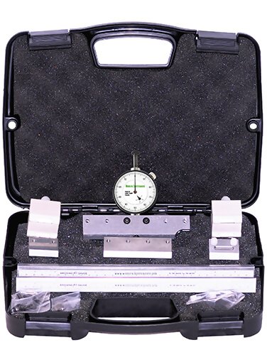
The Western Instruments N88-9 Bridging Pit Depth Gauge allows the CorrosionInspector to Span over or Cantilever into Large Areas of WeightLoss Corrosion, to obtain accurate and consistentmeasurements, or cross sections, of Pit Depth. As conditionsdictate, the operator can simply use the Main Blade or canassemble the Bridging Pit Gauge up to an over all length of28 (725mm). The contact Surfaces (Blades)of the Bridging Pit Gauge arefitted with an exclusive KnifeEdge, so they can be used onFlat, ID (Convex), and OD(Concave) Surfaces, where aflat or notched contact surfacecan introduces error onConvex Surfaces. Like ourStandard Pit Gauges, theKnife Edge gives the operatora clear view of the contactpoint, and the area being inspected. With the addition of the Magnetic Hold Downs, the operator uses their width to quickly align the Bridging PitGauge System to a curved surface. This leaves his hands free to scan through very large areas of weight loss corrosion.This holds true when the Bridge Elements have beenassembled with a slight contour on an irregular surface. 
Kit Contents

- N88-9 Bridging Pit Gauge Indicator (Inch, Metric or Digital)
- N88-9-1 Main Blade - Center and End Dial Indicator Mounting Positions, Fitted Permanent Magnets. Cutaway Nose for next to welds. 5.5 (144mm) long.
- N88-9-2 Connector Blade - Joins Tee Sections to increase length. 3.5" (90mm) long.
- N88-9-3 End Blade - Mounts on end of Tee for extra contact. 1.5 (38mm) long
- N88-9-4 Slider Blade - Extra Point of Contact and doubles as an End Blade inSpanning Configuration. 1.5 (38mm) long.
- N88-9-5 Extender Tees - Extends effective length of all models. 12 (305mm) long(Longer Tees are optional) - 2 (two)
- N88-9-6P Magnetic Hold Down Block- 2 (two)
- N88-9-7 Fastener Kit (Hardware) - Fasteners, Allen Key, Nylon Thumb Screws, #1 Contact Point-Standard.
- N88-9-8 Carrying Case - Hard Sided Plastic Carrying Case for entire kit
- Operator Manual
|  |

Features

Zeroing Dial Indicator - To quickly check the Zero Point of the Dial indicator, place the Blade on a representative smooth surface.
- Gently press the Plunger, until the contact point touches the surface.
- While the contact point is on the surface, loosen the Bezel Lock, and rotate the Bezel Scale until it reads '0' with respect to the pointer.
- Loosen the Fastener(s) holding the Dial Indicator in place.
- Hold the Blade firmly on a Flat Surface, and gently press the body of the Dial Indicator down until the contact point touches the flat surface.
- Carefully re-tighten the Clamp Fastener(s) or the Set Screw.
- Any fine zeroing can be done by rotating Bezel Scale on the Indicator.
- Height Zeroing should be done, whenever the unit is put into to use.
- Digital Indicators can be Height Zeroed or Positioned in the same way as a Mechanical Dial Indicator.
- To Zero the Digital Indicator simply press the Zero Button when the Contact Point is on a reference point. If the Digital Indicator is Height Zeroed, press Zero when the Plunger is fully retracted.
- To select Metric or Imperial Measurement, simply press the mm/in Button.Whennot in use, press the On/Off Button to turn the Indicator off.
- The position (or rotation) of the Dial indicator can be changed by simply loosening the Clamp Fasteners or Set Screw, and rotate the Dial Indicator about the Blade.
- After the Dial Indicator is rotated, the unit should be Dial Zeroed.

Specifications

Dial and Digital Indicators
 Measuring Corrosion (Depth) Measuring Corrosion (Depth)
* Western offers a variety of Contact Points, which are all 0.625" (16mm) long. Any ADG Contact point can be used with our specialdial indicators, but a different length may affect Height Zeroing, or the vertical position of the Dial Indicator. Contact Points are easily replaced, by extending the Contact Point , and turning it counter clockwise.

Related Products


Downloads

|
|
|